Tight tolerance machining is not simply “making a part more precisely.” It means controlling dimensional variation so a component fits and functions as designed. A difference of a few microns can affect a bearing seat, sealing face, or medical-device component. Yet tighter is not automatically better. It can raise cost, extend cycle time, and leave less room for process variation.
The stakes are growing as factories adopt more connected production methods. Deloitte and the Manufacturing Institute’s 2024 Smart Manufacturing Survey found that 86% of surveyed manufacturing executives expect smart manufacturing to be a primary driver of competitiveness within five years. That figure is not a machining-tolerance study. Still, it highlights why reliable process data and inspection matter. ASME Y14.5 also provides a widely used framework for communicating geometric dimensioning and tolerancing; a clear drawing is part of the control system, not an afterthought.
H. James Harrington, a quality-management expert, captured the role of measurement: “Measurement is the first step that leads to control and eventually to improvement.” The principle is practical. Check the machine’s thermal state, tool wear, workholding pressure, and measurement method before changing a toolpath. A cold machine and a warm machine may not produce the same result. Neither will a loose fixture and a rigid one. Learning how to handle tight tolerances in machining starts with identifying the source of variation, then matching the process and inspection plan to the part’s real functional needs. Even experienced teams can miss a hidden cause. That deserves a second look.
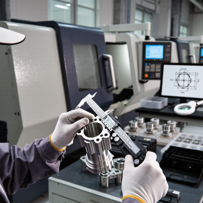
Tight-tolerance machining holds a part close to its specified dimensions. A tolerance of ±0.01 mm means the measured feature may vary by 10 μm above or below its nominal size. For a 25.00 mm shaft, the acceptable range is 24.99 to 25.01 mm. That creates a total tolerance band of 0.02 mm, or 20 μm. Small numbers, real consequences.
In practice, this range can be affected by tool wear, machine setup, cutting forces, and temperature. A metal part may expand slightly as it warms, while a burr can distort a reading. The drawing’s datum and measurement method matter too. A calibrated micrometer may suit a simple shaft; complex profiles often need a coordinate measuring machine. The instrument must have suitable resolution and verified calibration. A displayed number alone is not proof of accuracy.
Operators often check parts during production, not just at the end. That can reveal drift before a whole batch is affected. Still, measuring every feature to ±0.01 mm may add time and cost without improving function. I’ve seen a tolerance treated like a badge of quality; that assumption deserves a second look. Specify it where fit, movement, sealing, or alignment truly depends on it.
What Is Tight Tolerance Machining and How to Handle It?
ISO 2768-1 gives a useful baseline for dimensions without individual tolerances. Its medium, or class m, table allows ±0.2 mm for nominal dimensions from 6 to 30 mm. A 20 mm feature may therefore measure between 19.8 and 20.2 mm. That range is broad for a close-fitting assembly.
Treat the limit as a design decision, not a default guarantee. If a 20 mm pin must slide smoothly into a bore, allowing ±0.2 mm on both parts can create a 0.4 mm variation in their combined fit. Mark critical diameters, hole locations, and mating faces with specific tolerances. Then confirm the inspection method can reliably resolve them. A caliper may not be enough for every feature.
The reference is ISO 2768-1:1989, which provides general tolerance values for untoleranced linear and angular dimensions. Check that the drawing names the standard and class; otherwise, the shop may interpret the limits differently. Also review datum choices and stack-up across multiple features. A small oversight here can become an expensive rework later. And class m is not “tight” for every application. Use it deliberately, and question it when fit or function depends on a few tenths of a millimetre.
For nominal dimensions over 6 mm up to and including 30 mm, ISO 2768-1 gives the following general linear tolerances when the corresponding tolerance class is specified on the drawing.
How to read this chart: The bars show the permitted dimension range around a 20.00 mm nominal size. Class m allows 19.80–20.20 mm (±0.20 mm). General tolerances apply to dimensions without an individually stated tolerance; always specify critical features separately on the drawing.
Tight-tolerance machining starts with the function of each feature, not simply the smallest number on a drawing. A bearing seat may need a close diameter band, while a nearby clearance surface may not. Define critical dimensions and geometric relationships clearly. That matters. Unnecessarily tight tolerances can increase machining time, inspection effort, and scrap risk without improving performance.
Match the process to the tolerance band and part geometry. CNC turning suits precise cylindrical features; milling can control flat faces and pockets. Grinding may be appropriate when a hardened surface needs a fine finish and close dimensional control. For small internal details or difficult materials, electrical discharge machining can help, though its speed and surface condition may require trade-offs. Machine capability varies with setup, tool wear, part stiffness, and temperature, so confirm it with trial cuts or process data rather than assumptions.
Material choice affects the result. Aluminum machines readily, but thin sections can flex under clamping. Stainless steel may generate heat and work-harden, while some plastics expand noticeably with temperature. Consider stress relief, stock allowance, and the order of operations before cutting. Not always. A nominally stable material can still move after material is removed. Measure critical features with suitable calibrated instruments, and inspect parts near a controlled temperature. If results drift, revisit the fixture, cutting sequence, or measurement method before tightening the specification again.
Tight tolerance machining depends on repeatability, not a single impressive measurement. A target Cpk of 1.33 or higher gives the team a practical capability benchmark, but only when the process is stable and the measurements represent normal production.
Small shifts matter. A vise seating differently, a warm spindle, or a worn tool can move a bore toward its tolerance limit. Before cutting, clean locating faces, verify fixture contact, and record clamp settings. Warm the machine consistently, then check tool runout and work offsets with suitable measuring equipment.
During production, keep cutting conditions steady and monitor tool wear, coolant temperature, and part dimensions at planned intervals. Measure critical features with a calibrated instrument and use the same method each time. Plot the results; a Cpk value alone can hide a drifting process or inconsistent readings.
If capability falls short, check setup repeatability and measurement technique before changing several cutting variables at once. That advice is easy to give. In practice, teams sometimes overlook how a tiny burr on a locating surface affects the next setup. Recheck after tool changes and setup adjustments, and document what changed so later results can be interpreted reliably.
Tight tolerance machining is only dependable when inspection uncertainty is small beside the permitted variation. A coordinate measuring machine (CMM) can map hole positions, flatness, and datum relationships, but its reading is not exact. Probe choice, fixturing, temperature, and part cleanliness all matter. Small details matter.
For a 20.000 ±0.010 mm feature, the tolerance zone is 0.020 mm wide. A 4:1 test uncertainty ratio (TUR) means measurement uncertainty should be no greater than 0.005 mm. This is a useful decision benchmark, not a guarantee that every result is correct. ISO 10360-2 sets performance tests for Cartesian CMMs; verify that the machine’s tested capability suits the measurement task. NIST Technical Note 1297 explains expanded uncertainty using a coverage factor; k = 2 often corresponds to about 95% coverage when its distribution assumptions apply. Keep the calibration certificate and uncertainty statement with the inspection record. A polished report can still hide a weak setup. Recheck borderline parts with stable fixturing, controlled temperature, and a suitable probe, then document the decision rule and any repeat measurements.
Illustrative CMM inspection results for machined features. All dimensions are in millimeters. The test uncertainty ratio (TUR) is calculated as the full tolerance width divided by the expanded measurement uncertainty (U, k = 2).
| Feature | Nominal Size | Tolerance Limits | Measured Result | Full Tolerance Width | Expanded Uncertainty (U) | TUR | Result |
|---|---|---|---|---|---|---|---|
| Precision bore diameter | 20.000 | 19.980–20.020 | 20.006 | 0.040 | 0.008 | 5:1 | Within limits |
| Hole-center spacing | 50.000 | 49.970–50.030 | 49.992 | 0.060 | 0.012 | 5:1 | Within limits |
| Plate thickness | 8.000 | 7.950–8.050 | 8.018 | 0.100 | 0.020 | 5:1 | Within limits |
| Edge-to-datum distance | 35.000 | 34.960–35.040 | 35.011 | 0.080 | 0.016 | 5:1 | Within limits |
| Pin diameter | 6.000 | 5.985–6.015 | 5.997 | 0.030 | 0.0075 | 4:1 | Within limits |
TUR = full tolerance width ÷ expanded uncertainty. Results shown are illustrative; apply the applicable drawing requirements and documented decision rule when determining conformity.
A feature can measure 0.01 mm above or below its nominal size. For a 25.00 mm shaft, the acceptable range is 24.99 to 25.01 mm.
Tool wear, cutting forces, setup changes, and temperature can shift dimensions. Even a small burr can affect a reading. Tiny details matter.
No. Use close tolerances where fit, movement, sealing, or alignment depends on them. Tightening every dimension can add cost without improving function.
Turning often suits cylindrical features, while milling can control faces and pockets. Grinding may help with hardened surfaces. Geometry matters.
Thin aluminum sections may flex during clamping, while stainless steel can generate heat and work-harden. Some plastics also change size with temperature. It can be surprising.
Choose a calibrated instrument with suitable resolution. A micrometer may suit a simple shaft; complex profiles may need a coordinate measuring machine.
It is a capability benchmark for a stable process, not a guarantee by itself. A drifting process or inconsistent measurements can make the number misleading.
Check critical dimensions at planned intervals, especially after tool changes or setup adjustments. Track results and note what changed. Easy to miss.
Tight-tolerance machining is the controlled production of parts within a narrow range of permitted dimensional variation. For example, a tolerance of ±0.01 mm allows a deviation of just 10 μm from the specified dimension. Clear drawing limits are essential: under ISO 2768-1, Class m permits a general tolerance of ±0.2 mm for dimensions from 6 to 30 mm, which may be too broad for precision features. Specify tighter limits only where function requires them, and make sure the measurement method can verify those limits.
Knowing how to handle tight tolerances in machining starts with matching the process and material to the required tolerance band. Then stabilize the setup and cutting conditions to reduce variation, and aim for process capability of Cpk ≥1.33. Finally, verify critical dimensions with suitable CMM inspection and ensure the measurement system has a 4:1 test uncertainty ratio, so its uncertainty is sufficiently small compared with the tolerance being checked.

HYDRA CNC