Stamping tooling is the quiet force behind accurate, repeatable metal components. It guides sheet material through cutting, bending, drawing, and forming operations. A well-designed die can produce thousands of parts with consistent dimensions and clean edges. A poorly matched tool may create burrs, cracks, springback, or costly production delays.
So, what is the role of tooling in stamping processes? Its role extends far beyond shaping metal. Tooling controls material flow, supports dimensional accuracy, protects press equipment, and influences cycle time. It also affects operator safety, maintenance planning, scrap rates, and the final cost of each component. In a real production line, a few microns of die misalignment can become visible defects across an entire batch.
This guide examines the top 10 roles of tooling in stamping processes. It considers practical issues from die selection and guided movement to lubrication, wear monitoring, and quick changeovers. Experienced toolmakers often inspect witness marks, punch edges, and clearance settings before approving a run. Small details matter.
Not every tool performs perfectly. Material variation, inaccurate setup, and overlooked wear can challenge even a proven design. That limitation deserves attention. Reliable results require engineering calculations, trial stamping, documented inspections, and feedback from operators. Using these controls, manufacturers can improve quality without treating tooling as a one-time purchase. The strongest approach combines technical knowledge with evidence from the shop floor.
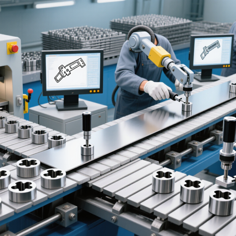
Top 10 Roles of Tooling in Stamping Processes
Understanding tooling starts with the part geometry, material, and production volume. Blanking dies cut the outside profile. Piercing dies create holes. Forming dies bend flanges and ribs. Drawing dies pull flat sheets into cups or housings. Embossing tools add marks, channels, or stiffening patterns. Trimming dies remove unwanted edges after forming. These tools control shape, repeatability, and material flow. A compound die performs several cutting actions in one stroke. Progressive dies move a strip through multiple stations. Transfer dies move separate blanks between forming stages. Tool selection changes with tolerance, thickness, and batch size.
Scale makes tooling discipline important. The World Steel Association reported about 1.89 billion tonnes of crude steel production in 2023. Even small scrap differences matter across high-volume lines. A 2024 smart-manufacturing survey found 86% of industrial leaders viewed connected production as a major competitiveness driver. Sensors now monitor force, stroke, temperature, and die wear. Useful data, but not magic.
Shop-floor trials often reveal the overlooked problem: a well-designed die can still fail after poor setup. Clearance, lubrication, alignment, and coil flatness need daily attention. One missed adjustment can leave burrs or wrinkles. A perfect die is a useful myth. Engineers should review first-run parts, not trust drawings alone. Maintenance records also expose weak assumptions, especially when punch edges wear faster than expected. That reflection improves the next tooling revision.
| No. | Tooling Role | Typical Tooling Type | Primary Function | Typical Process Stage | Main Outputs | Quality Impact |
|---|---|---|---|---|---|---|
| 1 | Material Positioning | Die set, guide posts, guide bushings, and pilots | Locates the strip or individual blank accurately before each forming or cutting operation and maintains alignment between the upper and lower die sections. | Loading and feeding | Consistent part location and repeatable stroke-to-stroke registration | Reduces positional variation and misalignment |
| 2 | Blanking and Part Separation | Blanking die or compound die | Uses a punch and die opening to cut the required outside profile from sheet or strip material. | Cutting | Individual blanks or finished outer profiles | Controls profile accuracy, burr formation, and edge condition |
| 3 | Piercing and Hole Making | Piercing punch, die button, and stripper | Produces holes, slots, and other internal openings by shearing material through accurately matched punch and die components. | Piercing | Mounting holes, slots, vents, and locating features | Maintains hole diameter, position, roundness, and burr control |
| 4 | Bending and Flanging | Forming die, wipe die, and bending punch | Applies a controlled bending force to create angles, flanges, hems, channels, and other linear forms. | Forming | Defined bends, flanges, and structural edges | Influences bend angle, springback, cracking, and dimensional stability |
| 5 | Drawing and Deep Forming | Draw die, punch, blank holder, and draw beads | Transforms a flat blank into a cup, shell, or three-dimensional component by controlling material flow into the die cavity. | Deep drawing | Seamless shells, cups, housings, and enclosed forms | Helps prevent wrinkles, tearing, excessive thinning, and uneven wall height |
| 6 | Progressive Multi-Operation Processing | Progressive die with multiple stations | Combines sequential operations such as piercing, blanking, bending, and forming while the strip advances through the die. | High-volume production | Completed parts from a continuous strip in one press cycle sequence | Improves throughput and process consistency while reducing handling |
| 7 | Compound Cutting and Forming | Compound die | Performs two or more cutting actions, or cutting and limited forming, during a single press stroke. | Single-stroke production | Flat or lightly formed parts with multiple features | Improves feature-to-feature location because operations occur in one setup |
| 8 | Material Holding and Stripping | Pressure pad, blank holder, fixed stripper, or spring stripper | Holds the workpiece against the die or removes the material from the punch after cutting and forming. | Cutting and forming support | Stable workpiece contact and reliable part release | Reduces material lift, distortion, scratches, and feeding interruptions |
| 9 | Part Ejection and Transfer | Ejector pins, lifters, air ejectors, and transfer tooling | Removes completed parts from the die area and transfers them to the next station or collection point without damaging critical features. | Discharge and transfer | Reliable part removal and controlled movement between operations | Supports automation, prevents part collisions, and lowers stoppage risk |
| 10 | Process Control and Tool Life Management | Replaceable inserts, wear plates, sensors, and maintenance features | Controls wear-prone areas, monitors selected process conditions, and enables replacement or adjustment of critical tooling components. | Inspection and maintenance | Stable process conditions and planned tool servicing | Extends usable tool life and helps maintain part quality over production runs |
The die guides material flow under pressure. Punch geometry controls bends, corners, radii, and tearing risks. Small design errors can multiply across production.
Clearance affects edge quality, dimensions, burrs, and tool wear. Excessive clearance may create rough fracture zones. Tight clearance can increase force and wear.
Polished forming areas reduce scoring and drag marks. Suitable lubrication helps prevent galling. Surface defects may reveal alignment problems early.
Draw beads regulate how metal moves through the die. Poor adjustment can cause wrinkles or excessive thinning. The setup may need another trial.
Stable guides, pilots, and locating surfaces reduce misfeeds and press stops. Progressive stations can combine several operations in one pass. Less handling saves time.
Accurate nesting and controlled blanking reduce scrap between parts. Designers consider coil width, grain direction, forming depth, and springback. Savings are not automatic.
They should check pilots, guide posts, clearances, fasteners, lubrication points, and cutting edges. A loose locating surface can distort thousands of parts.
They should record thickness, hole locations, height, width, surface condition, and springback. Regular inspections reveal wear before defects spread. No setup is perfect.
Uneven tool wear, temperature changes, and material variation can shift results. A tool may run quickly while accuracy slowly declines. That deserves review.
Tooling plays a central role in stamping by shaping raw material into accurate, repeatable components. What is the role of tooling in stamping processes? It includes selecting and using dies, punches, guides, holders, and supporting fixtures to prepare materials, position them correctly, and control each forming, cutting, bending, or drawing operation. Well-designed tooling determines the final shape, dimensions, tolerances, and surface condition of stamped parts while reducing distortion and production defects.
Effective tooling also improves manufacturing efficiency by enabling faster cycles, consistent results, and better use of sheet material. Proper layouts and controlled forming paths can reduce scrap, while reliable guidance and support promote safe, stable operation. Tooling must also be designed for inspection, cleaning, adjustment, and maintenance so that production interruptions remain limited. In addition, modular or adaptable tooling can support different part designs, process improvements, and changing production requirements. Overall, tooling connects material preparation, process control, quality assurance, productivity, safety, and long-term manufacturing flexibility.

 HYDRA CNC